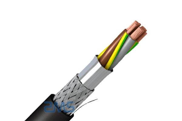


Establishing a low-impedance connection between the circuit ground and the chassis within the I/O area can also be advantageous with respect to radio frequency (rf) immunity. This connection should be a low-impedance connection at radio frequencies. However, to be efficient at RF, the parasitic inductance of the capacitors should be as little as attainable. The actual implementation of an effective hybrid cable shield floor might, nevertheless, be difficult, because any inductance in sequence with the capacitor will decrease its effectiveness. Didn’t I just write that “terminate the shield at chassis on each ends, never the circuit ground”? However, bonding circuit floor and chassis is usually fascinating due to different sensible issues, primarily ESD. The connection of the shield is subjected to multiple and sometimes contradictory requirements: (1) effective RF shielding, (2) avoiding floor loops that cause low-frequency noise and hum, (3) ESD immunity, (4) radiation due to common-mode present flowing throughout the shield or chassis. After the metal enclosure is zapped by ESD, the circuit floor potential is held by the cable, enabling a secondary ESD strike might develop from the chassis to the circuit ground, finally leaving the system via an hooked up cable.
Unfortunately, real circuit boards have exterior cables connected, and one of the cable might attach the circuit ground to an external floor, possibly an Earth floor. Analog information acquisition systems might experience similar problems. What is the solution for blended-signal programs? If terminating the shield at each sides is required for top-frequency shielding, whereas terminating the shield at one side is required for low-frequency analog methods to keep away from mains hum. If the bottom aircraft is bonded to the chassis at the fitting aspect of the board, while the cable enters at the left side of the circuit board, this potential distinction would trigger a common-mode noise present to stream, degrading the EMI/EMC performance of the system. Connecting the shield at each ends create a ground loop, a small difference of ground potential causes a noise current to movement from one finish to a different. By connecting the shield, chassis, and circuit ground at nearly the identical location, a voltage gradient is largely avoided. In my unique reply, I believed I already rigorously navigated across the nuisances of the professionals and cons of connecting the shield at one side, or at each sides.
Wait three seconds. Then plug the shield again into the Arduino and as quickly as you may sort a bunch of ‘x’s into the Hyperterminal window. Wait till you see the not-red gentle on the side of the Pi cease blinking and exit completely. Thus, the shield is commonly related at one end, and disconnected at the opposite aspect. Thus, except very excessive isolation is required, splitting the analog and digital ground planes is commonly counterproductive. However, at excessive frequency, the capacitor becomes a low impedance, which converts the circuit to 1 that’s grounded at each ends. Note that the charger which comes with customary norns is rated for 2A / 5.25V. This brick is of very high quality and may use 110 or 240 VAC input, so it can be utilized outside of the US with a simple plug format adapter. These are chosen by the script’s author and might be adjusted through the use of E3. Considering the decline of component programs, there are mainly two common situations where CEC is used as we speak. Computers almost universally do not, as cost and licensing considerations imply that GPUs do not provide a CEC transceiver.
Here’s more in regards to shield control cable check out our own web-site.


